
Start Right Here Find appliance parts, lawn & garden equipment parts, heating & cooling parts and more from the top brands in the industry here. Click on Shop Parts, or select the kind of product you're working with on the left and we'll help you find the right part. MHA Series Unit Single-Zone Mini-Split System (Heat Pump Only) - MHA Series Unit Information MLA, MPA, MPB and 3PB Single and Multi-Zone Outdoor Units wih Compatible Indoor Units Service Manual Packaged Elec/Elec / Heat Pump.
The tables below contain the lists of possible breakdowns which may happen with Lennox heat pumps of different modifications. In case of Lennox heat pump not working you should address these checklists.


There are types of faults and problems with detailed descriptions, possible causes and solutions which may be recommended in the certain situations. If you feel the temperature in your house is getting higher, it may be because of heat pump fan not spinning, and therefore, heat pump not cooling. The information given below can be helpful for you then.
Lennox 2SHP13 Heat Pump Troubleshooting
| Green LED (DS2) | Red LED (DS1) | Mode |
|---|---|---|
| Off | Off | No Power to Board |
| Simultaneous Slow Flash | Simultaneous Slow Flash | Normal Operation/ Power to Board |
| Alternating Slow Flash | Alternating Slow Flash | Anti-Short Cycle Lockout |
| Off | Slow Flash | Low Pressure Switch Fault |
| Off | On | Low Pressure Switch Lockout |
| Slow Flash | Off | High Pressure Switch Fault |
| On | Off | High Pressure Switch Lockout |
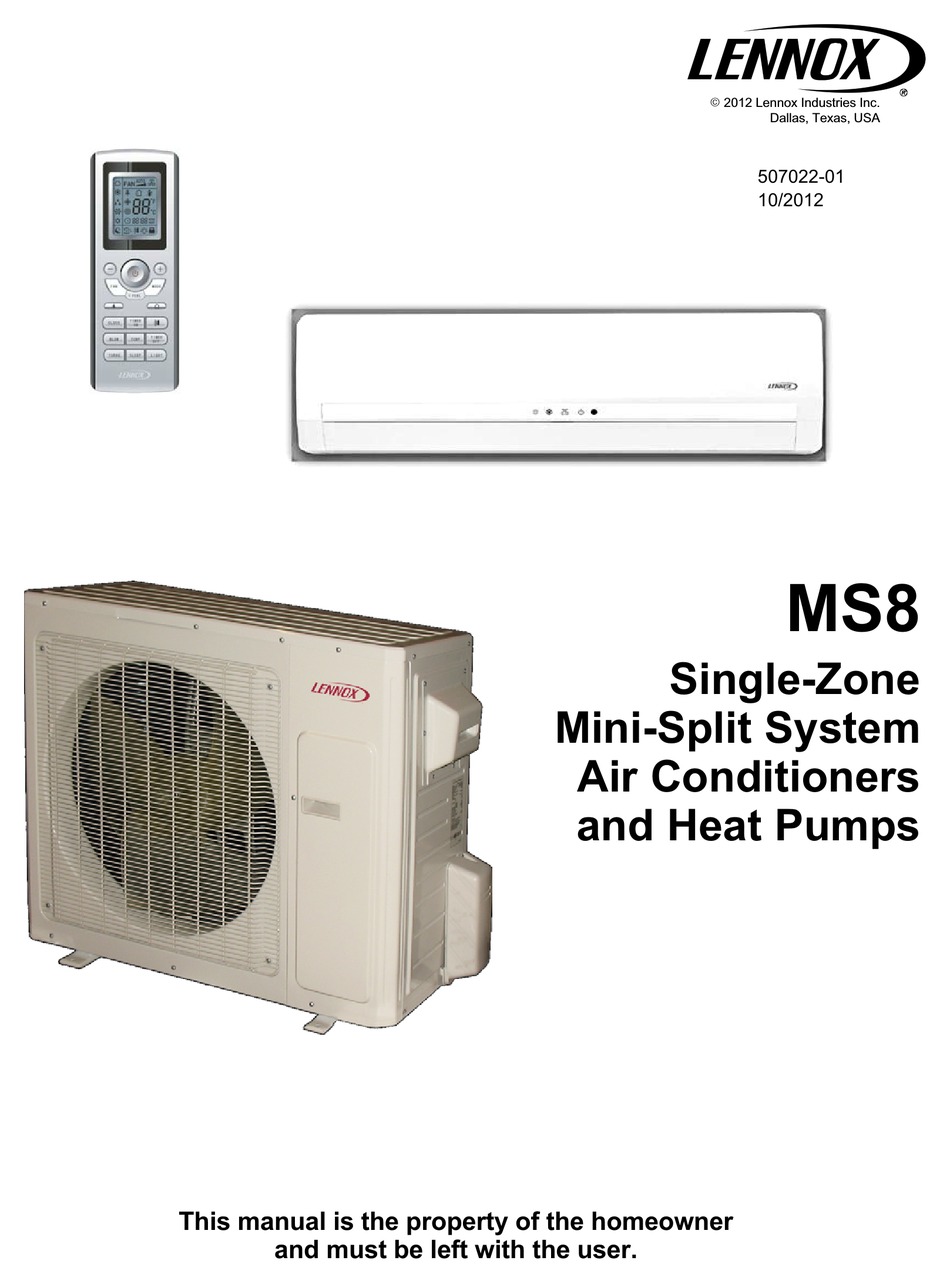
Lennox Mini Split Ms8 User Manual Free
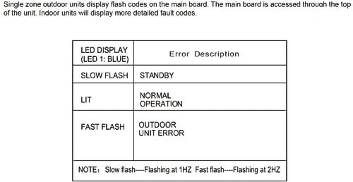
Lennox MS8 Heat Pump Troubleshooting
| Problem | Possible Cause |
|---|---|
| Unit does not operate immediately when restarted. | Unit control initiates a 3-minute delay at the end of each cycle to protect the compressor from damage. |
| A whoosh or gurgling noise can be heard at the indoor unit. | Sometimes, the refrigerant can be heard in the indoor coil when the outdoor unit starts or stops operation. This is not a malfunction. |
| Mist is coming out of the indoor unit during cooling operation. | This sometimes happens when the indoor temperature and humidity are very high and the air is being cooled quickly. The mist will disappear as the indoor temperature and humidity are lowered. |
| A creaking or popping noise can be heard when the unit starts or stops. | The plastic components of the indoor units sometimes expand and con- tract when they are heated and cooled. |
| Unit is not operating. | Are the TIMER ON and TIMER OFF features being used incorrectly? |
| Is power disconnected or has circuit breaker tripped. | |
| Is power shut down? | |
| System is not cooling (or heating) efficiently. | Is temperature setting correct? |
| Are either the air inlet or air outlet blocked on the outdoor or indoor unit? | |
| Is filter dirty? | |
| Is fan at low speed? | |
| Are windows and doors properly shut? | |
| Wireless remote is not working. | Is remote in direct line of sight with indoor unit infrared receiver? Has the remote been damaged? |
| Remove remote control batteries for 30 seconds, then reinsert them. Replace batteries, if necessary. | |
| Water is leaking from indoor unit. | Indoor humidity level is very high and water is being blown from indoor coil. This will stop as humidity level is reduced. |
| Water is leaking from condensate line at Water is leaking from condensate line at indoor unit.indoor unit. | Check condensate line outside to make sure it is not obstructed. |
| Check condensate line to make sure it has not been disconnected from indoor unit. | |
| Water is leaking from the outdoor unit. | During operation in high-humidity areas, condensate will form on cold outdoor refrigerant pipes. |
| When heat pump is operating in defrost mode, ice will thaw from around outdoor coil and water will flow from the unit. | |
| Clicking noise heard inside. | Sometimes, the sound of the outdoor unit fan or compressor relay can be transmitted in a way that makes it seem to be coming from the indoor unit. |
| Indoor fan is not working. | Heat pump units - In HEAT mode, a timed delay keeps indoor fan off for two minutes to prevent unheated air from being circulated by the indoor fan. |
| Heat pump units - In HEAT mode, cold outdoor temperatures and high humidity cause frost to accumulate on the outdoor unit. When this hap- pens, the unit will enter a defrost cycle. The indoor fan is off during the 3 -12 minute cycle. | |
| In DEHUMIDIFICATION mode, indoor fan operation may be stopped to avoid delivery of moist air to the room. Do not adjust temperature set- ting. |
Lennox XPG20 Heat Pump Troubleshooting
| Green | Red | Code | Cause | Solution |
|---|---|---|---|---|
| OFF | OFF | Power problem | No power (24V) to board terminals R & C or board failure. | Check control transformer power (24V). |
| If power is available to board and LED(s) do not light, replace board. | ||||
| Simultaneous SLOW Flash | Simultaneous SLOW Flash | Normal operation | Unit operating normally or in standby mode. | None required. |
| Alternating SLOW Flash | Alternating SLOW Flash | 5-minute anti-short cycle delay | Initial power up, safety trip, end of room thermostat demand. | None required (Jumper TEST pins to override) |
| Simultaneous FAST Flash | Simultaneous FAST Flash | Ambient Sensor Problem | Sensor being detected open or shorted or out of temperature range. Board will re- vert to time/ temperature defrost operation. (System will still heat or cool). | |
| Alternating FAST Flash | Alternating FAST Flash | Coil Sensor Problem | Sensor being detected open or shorted or out of temperature range. Board will not perform demand or time/ temperature defrost operation. (System will still heat or cool). | |
| ON | ON | Circuit Board Failure | Indicates that board has internal component failure. Cycle 24 volt power to board. If code does not clear, replace board. | |
| OFF | SLOW Flash | Low Pressure Fault | Restricted air flow over indoor or outdoor coil. | Remove any blockages or restrictions from coils and/or fans. Check indoor and outdoor fan motor for proper current draws. |
| OFF | ON | Low Pressure LOCKOUT | Improper refrigerant charge in system | Check system charge using approach & sub- cooling temperatures. |
| SLOW Flash | OFF | High Pressure Fault | Improper metering device installed or incorrect operation of metering device | Check system operating pressures and compare to unit charging charts. |
| ON | OFF | High Pressure LOCKOUT | Incorrect or improper sensor location or connection to system. | Make sure all pressure switches and sensors have secure connections to system to prevent refrigerant leaks or errors in pressure and temperature measurements. |
| SLOW Flash | ON | Discharge Line Temperature Fault | This code detects shorted sensor or high discharge temperatures. If the discharge line temperature exceeds a temperature of 285°F (140°C) during compressor operation, the board will de-energize the compressor contactor output (and the de- frost output if active). The compressor will remain off until the discharge temperature has dropped below 225°F (107°C). | |
| FAST Flash | ON | Discharge Line Temperature LOCKOUT | ||
| OFF | Fast Flash | Discharge Sensor Fault | The board detects open sensor or out of temperature sensor range. This fault is detected by allowing the unit to run for 90 seconds before checking sensor resistance. If the sensor resistance is not within range after 90 seconds, the board will count one fault. After 5 faults, the board will lockout. | |
| Fast Flash | OFF | Discharge Sensor LOCKOUT |
Lennox FCM 85 Heat Pump Troubleshooting
Lennox Mini Split Ms8 User Manual Model
| STAGE | NORMAL OPERATION | POSSIBLE FAULT | ACTION | POSSIBLE SOLUTION |
|---|---|---|---|---|
| Heating Requested | Extraction fans start | Fault on the Blower thermostat | + Check connections on the blower thermostat. | + Replace thermostat |
| Lack of gas supply | + Check valve’s opening & supply pressure | + Restore gas supply | ||
| Fault on the superheat thermostat on the gas burner support bar | + Check superheat thermostat’s operation after manual reset | + Replace superheat thermostat | ||
| Starting of the extraction fans | Extraction Fans are running | After 10 seconds safety shutdown by the ignition control block | + Check connections of the control block on the gas valve | + Repositioning of the control block on the valve + Replace valve |
| Nothing happens | + Check the free movement of the fan wheel + Check Electrical connection on the Gas Ignition Control Block and on EF connection Board | + Replace fan + Replace EF connection board If necessary | ||
| + Check the Fan supply voltage | ||||
| Extraction Fan is ON | After 30 to 45 seconds: pre- ventilation the fire-up electrode should spark. | Continuous Ventilation without sparks from fire-up electrode | + Check the fire-up electrode + Check the pressure drop at the pressure switch: It must be higher than 165 Pa +Check the good operation of the pressure switch using an Ohmmeter and by artificially creating a depression in the tube. | + Re-position the pressure switch tube. |
| + Change the pressure switch. | ||||
| Continuous ventilation and sparks from fire up electrode. | After a few seconds the gas burner fires-up | After 4 seconds the GAS Burner still not operating and safety shutdown by the Ignition Control Block. | + Check injection pressure during start-up (Value for High Heat) | + Remove the air from the Gas pipe-work + Adjust the injection pressure to high heat value. |
| +Remove the control box from the gas block. | + Change the Control Box if the Gas valve is OK. | |||
| Within 4 seconds the gas Burner fires-up BUT safety shutdown from the Ignition Control Block. | + Check the Position and connection of the Ionization Probe. It must not be Earthed (230V). | +Check the whole electrical supply. | ||
| + Measure the Ionization Current: It must be higher than 1.5 microAmps. | + Adjust the supply and injection pressure if gas is different from natural gas G20 | |||
| + Check the Type of GAS. |
Lennox XP15 Heat Pump Troubleshooting
| Status LED Condition | Status LED Description | Status LED Troubleshooting Information |
|---|---|---|
| Green Power LED ON | LSOM has power | 24VAC control power is present at the LSOM terminal. |
| Green Power LED OFF | LSOM not powering up | Determine/verify that both R and C LSOM terminals are connected and voltage is present at both terminals |
| Red Trip LED ON | System and compressor check out OK | 1 Verify Y terminal is connected to 24VAC at contactor coil. |
| 2 Verify voltage at contactor coil falls below 0.5VAC when off | ||
| 3 Verify 24VAC is present across Y and C when thermostat demand signal is present: if not present. R and C wires are reversed. | ||
| Thermostat demand signal Y1 is present, but compressor not running NOTE - During 5-minute delay in LSOM the red trip LED will be on. | 1 Compressor protector is open. | |
| 2 Outdoor unit power disconnect is open. | ||
| 3 Compressor circuit breaker or fuse(s) is open. | ||
| 4 Broken wire or connector is not making contact. | ||
| 5 Low pressure switch open if present in the system. | ||
| 6 Compressor contactor has failed to close | ||
| Red Trip and Yellow Alert LEDs Flashing | Simultaneous flashing. | Indicates that the control circuit voltage is too low for operation |
| Yellow Alert Flash Code 1 | Long Run Time - Compressor is running extremely long run cycles | 1 Low refrigerant charge. |
| 2 Evaporator blower is not running. | ||
| 3 Evaporator coil is frozen. | ||
| 4 Faulty metering device | ||
| 5 Condenser coil is dirty | ||
| 6 Liquid line restriction (filter drier blocked if present)- | ||
| 7 Thermostat is malfunctioning | ||
| Yellow Alert Flash Code 2 | System Pressure Trip - Discharge or vapor pressure out of limits or compressor overloaded | 1 Check high head pressure or discharge line sensor. |
| 2 Condenser coil poor air circulation (dirty, blocked, damaged) | ||
| 3 Condenser fan is not running. | ||
| 4 Return air duct has substantial leakage. | ||
| 5 If low pressure switch is present, see Flash Code 1 information. | ||
| Yellow Alert Flash Code 3 | Short Cycling - Compressor is running only briefly | 1 Thermostat demand signal is intermittent. |
| 2 Time delay relay or DCB is defective. | ||
| 3 If high pressure switch is present, see Flash Code 2 information | ||
| 4 If low pressure switch is present, see Flash Code 2 information | ||
| Yellow Alert Flash Code 4 | Locked Rotor | 1 Run capacitor has failed. |
| 2 Low line voltage (contact utility if voltage at disconnect is low). | ||
| 3 Excessive liquid refrigerant in the compressor. | ||
| 4 Compressor bearings are seized. | ||
| Yellow Alert Flash Code 5 | Open Circuit | 1 Outdoor unit power disconnect is open. |
| 2 Unit circuit breaker or fuse(s) is open. | ||
| 3 Unit contactor has failed to close. | ||
| 4 High pressure switch is open and requires manual reset. | ||
| 5 Open circuit in compressor supply wiring or connections. | ||
| 6 Unusually long compressor protector reset time duo to extreme ambient temperature. | ||
| 7 Compressor windings are damaged | ||
| Yellow Alert Flash Code 6 | Open Start Circuit - Cur- rent only in run circuit | 1 Run capacitor has failed. |
| 2 Open circuit in compressor start wiring or connections. | ||
| 3 Compressor start winding is damaged | ||
| Yellow Alert Flash Code 7 | Open Run Circuit - Current only in start circuit | 1 Open circuit in compressor start wiring or connections |
| 2 Compressor start winding is damaged | ||
| Yellow Alert Flash Code 8 | Welded Contactor - Compressor always runs | 1 Compressor contactor failed to open |
| 2 Thermostat demand signal not connected to LSOM | ||
| Yellow Alert Flash Code 9 | Low Voltage - Control circuit <17 VAC | 1 Control circuit transformer is overloaded. |
| 2 Low line voltage (contact utility if voltage at disconnect is low). |